

Why and how to calibrate a machine vision system?
Calibrating a machine vision system serves two purposes
The first is to convert pixel coordinates into real-world units, typically mm or inches. Whilst pixels have relative positions or sizes they have no inherent scale and are meaningless in the real-world. Typically a system is calibrated by imaging an object of known size, enabling the vision system to locate particular features and compute a scaling factor.
A calibration target, often a grid, is useful for this procedure as it also addresses the second purpose of calibration, this is to remove lens distortion. A camera lens will almost certainly introduce distortion, especially radial distortion, whereby straight lines appear curved.
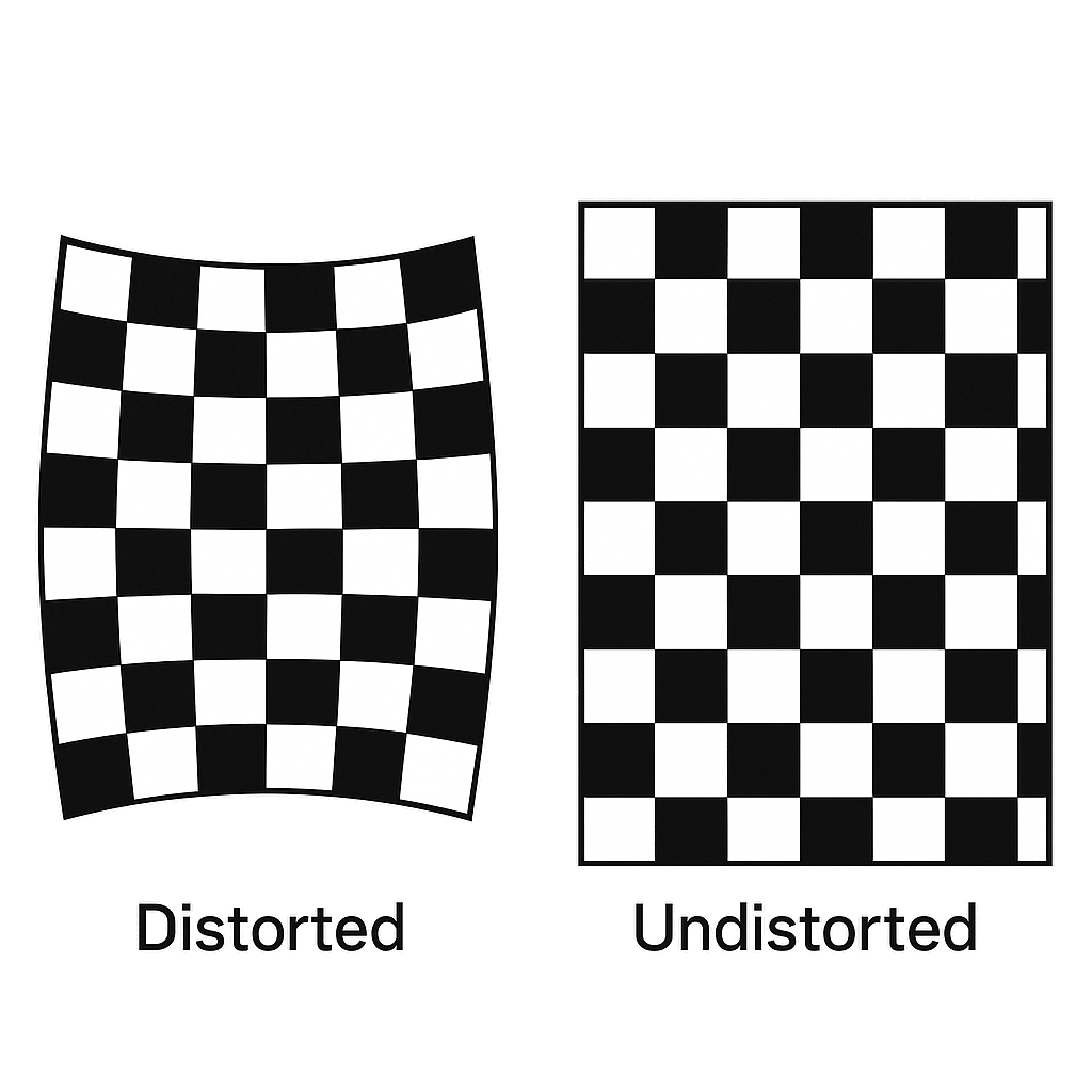
During the calibration process the distortion is modelled. This model can be applied to each subsequent acquired image allowing it to be undistorted or corrected. In the undistorted image relationships between features are preserved but lines which are straight in the real world are straight in the image and all other features retain their size and orientation.
With distortion removed image pixels can be mapped to real world units allowing accurate measurements across the entire image.
In Summary
Calibration has two main purposes. To remove lens distortion and to convert pixel coordinates into real world values.
Lens distortion can make straight lines appear curved, especially close to the edges of the image. This results in an image that is not a true geometric representation of the real world.
Distances between features are meaningless in physical terms if they are measured only in pixels.
Calibration targets are often made of features aligned in a grid pattern. This ensures that features are distributed across the entire image and helps expose distortion effectively, particularly because regular patterns make geometric deviations easier to detect.
Working With Oculus Vision
If you need support with vision system calibration or metrology on a current project, we are happy to discuss the application.